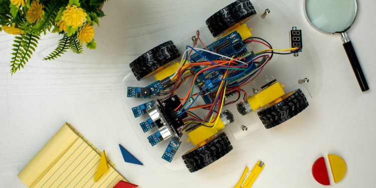
One of the most exciting aspects of working with the Arduino Beginner Kit is the ability to create visually stunning projects using LEDs. While single-color LEDs are great for simple projects, RGB LEDs open up a world of possibilities by allowing you to create virtually any color by mixing red, green, and blue light. In this post, we’ll explore how to connect and control RGB LEDs with your Arduino, and we’ll guide you through a fun project to get you started.
What is an RGB LED?
An RGB LED is essentially three LEDs in one package: red, green, and blue. By adjusting the brightness of each of these three LEDs, you can create a wide range of colors. RGB LEDs come in two types: common cathode and common anode. In a common cathode RGB LED, all the cathodes (negative terminals) are connected together, while in a common anode RGB LED, all the anodes (positive terminals) are connected together.
Components Needed
- Arduino Uno
- RGB LED
- Resistors (220 ohm recommended)
- Breadboard
- Jumper wires
Wiring the RGB LED
For this example, we’ll use a common cathode RGB LED. Follow these steps to connect the LED to your Arduino:
- Identify the Pins:
- The RGB LED has four pins: one for each color (red, green, blue) and one common cathode.
- The longest pin is the common cathode.
- Connect the Cathode:
- Connect the longest pin (common cathode) to the GND (ground) on the Arduino.
- Connect the Red Pin:
- Connect a 220-ohm resistor to the red pin of the RGB LED.
- Connect the other end of the resistor to digital pin 9 on the Arduino.
- Connect the Green Pin:
- Connect a 220-ohm resistor to the green pin of the RGB LED.
- Connect the other end of the resistor to digital pin 10 on the Arduino.
- Connect the Blue Pin:
- Connect a 220-ohm resistor to the blue pin of the RGB LED.
- Connect the other end of the resistor to digital pin 11 on the Arduino.
Writing the Code
Now that we’ve wired the RGB LED, it’s time to write the code to control it. We’ll create a simple program that cycles through different colors by adjusting the brightness of each color component.
cpp
Copy code
int redPin = 9; int greenPin = 10; int bluePin = 11;
void setup() { pinMode(redPin, OUTPUT); pinMode(greenPin, OUTPUT); pinMode(bluePin, OUTPUT); }
void loop() { setColor(255, 0, 0); // Red delay(1000); setColor(0, 255, 0); // Green delay(1000); setColor(0, 0, 255); // Blue delay(1000); setColor(255, 255, 0); // Yellow delay(1000); setColor(0, 255, 255); // Cyan delay(1000); setColor(255, 0, 255); // Magenta delay(1000); setColor(255, 255, 255); // White delay(1000); }
void setColor(int red, int green, int blue) { analogWrite(redPin, red); analogWrite(greenPin, green); analogWrite(bluePin, blue); }
Uploading and Running the Code
- Connect your Arduino:
- Use a USB cable to connect your Arduino to your computer.
- Open the Arduino IDE:
- Open the Arduino IDE on your computer.
- Copy and paste the code above into a new sketch.
- Select the Correct Board and Port:
- Go to Tools > Board and select Arduino Uno.
- Go to Tools > Port and select the port your Arduino is connected to.
- Upload the Code:
- Click the upload button (right arrow icon) to upload the code to your Arduino.
- Watch the Colors:
- Once the code is uploaded, your RGB LED should start cycling through different colors, changing every second.
Conclusion
Controlling RGB LEDs with Arduino is a great way to add colorful visual effects to your projects. By understanding how to wire and program RGB LEDs, you can create dynamic lighting displays, indicators, and more. Experiment with different color combinations and patterns to make your projects even more impressive. As you become more comfortable with RGB LEDs, you can integrate them into more complex projects, such as mood lights, interactive displays, and custom light shows. The possibilities are endless!


